Measuring Current
The size of current flowing through a circuit depends on:
As electrons pass through a cell or power supply they gain energy. The difference in energy between electrons entering and leaving the cell is called the potential difference (p.d.) or voltage. There is also a potential difference across every component in a circuit, because energy is transferred to them as the current flows through. The bigger the potential difference across a component, the bigger the current that flows through it. Resistance is measured in ohms (Ω) The current flowing through a component is measured in amperes (A) using an ammeter connected in series with the component. | |||||||||||||||||||
Circuit Diagrams and Symbols
| |||||||||||||||||||
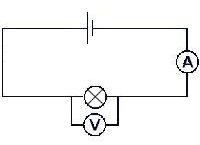
The diagram shows how the current flowing through a lamp and the p.d. across it can be measured. If the voltage of the power supply is altered, the current through the filament lamp and voltage across it would alter as shown in the current-voltage graph below. |
| ||||||||||||||||||
| |||||||||||||||||||
Ohm's Law
A diode only allows current to flow through in one direction, because it has a high resistance in the opposite direction. The resistance of a light dependent resistor decreases as the light intensity increases. The resistance of a thermistor decreases as the temperature increases. | |||||||||||||||||||
Series and Parallel Circuits
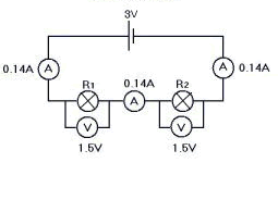
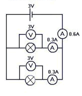
When cells are connected in series their total p.d. is the sum of them all. | |||||||||||||||||||
Document Actions


 Like us on Facebook